reputation_scoree
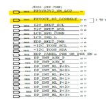
I have one 820-4924 for repairs . all voltages on connector j8300 are missing . There is dim display on panel. i have changed the brightness ic. Is there any demo of step by step functioning of the led.
reputation_scoree
reputation_scoree
reputation_scoree
WHAT TO DO WHEN THERE IS NO BACKLIGHT ON A MACBOOK?I have one 820-4924 for repairs . all voltages on connector j8300 are missing . There is dim display on panel. i have changed the brightness ic. Is there any demo of step by step functioning of the led.

reputation_scoree
Some voltages will only be created if a display is connectedon pin no 3 and 4 i am getting 5v.
pin no 1, 5 , 6, 7, 8 and 9 voltages are 0
reputation_scoree
reputation_scoree
Reputation:
First make sure you get the EDP_BKLT_EN, trace it back where it came from.EDP_BKLT_PWM and EDP_BKLT_EN both these signals are missing. Now which signal should i check ?
reputation_scoree
reputation_scoree
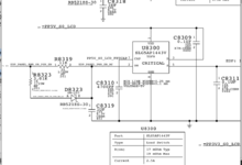
It is enabled on U8330, it is very possible that it is the reason for the failure. It is a smd dual input NOR gate.from cpu. I dont know what is the input signal to cpu which enables EDP_BKLT_EN.
reputation_scoree
U8330EDP_BKLT_PWM and EDP_BKLT_EN both these signals are missing. Now which signal should i check ?
reputation_scoree
In the case of Apple computers, the backlight circuit is on the motherboard rather than on the screen (as opposed to how IBM PC-based brands do). This is the main reason why laptop screens cannot be used on a MacBook. This design also makes the MacBook particularly vulnerable to water damage. Water can instantly kill the backlight circuit, which for proper operation must fluctuate between 28V and 50V to be considered normal. To measure this, the display needs to be connected to the logic board when performing power tests.is there any theoratical explanation regarding the step by step process of LED. Means how led function. Total communication of led with motherboard. First signal to led to the last signal. Proper theory of the subject is confidence. Pls show me a site where i can get detail knowledge. Thanks
Reputation:
Have u checked U8300 Pin 2, Pin 1?from cpu. I dont know what is the input signal to cpu which enables EDP_BKLT_EN.
reputation_scoree
reputation_scoree
Reputation:
Ok, so trace the voltage back from where it comes from.. and post updates here. you need to try harder..on pin no 2 enable signal is 0v.
")
reputation_scoree
Reputation:
reputation_scoree
If it refers to pin 2 of U8300, check C8319, D8323 R8319, if ok, replace U8300 (LED backlight power supply).on pin no 2 enable signal is 0v.
reputation_scoree
I understood at the beginning of the thread that everything worked except the display backlight so you only need to focus on the U8300 and U8330.The more detailed updates you post, the sooner you can have this fixed. we need to know what state your laptop is stuck in.
- How much amperage do u get on the power supply?
- Post all the voltages u have taken so far, from DC_IN, VCCRTC, SMC_BC_ACOK, VCCSUS3_3, HALL SENSOR, PM_BATLOW and so on..?
- Did u check the pins on the bios and clock frequencies, data in/output? pin 2, pin 5, pin 6, all 7 pins?
Also try to mention whats the history of the computer. What happened to it?
reputation_scoree
It does not come from the CPU, it is enabled in U8300, backlight power supply and U8330 is used so that the rail EDP_PANEL_PWR_PSR_EN USE TO DOWNLOAD THE LCD BEFORE THE POWER IS TURNED OFF comes from cpu. I dont know which signal is the input to the cpu to trigger ON the backlit section
reputation_scoree
There are currently 0 members watching this topic
Tara Laptops , Hosein Asadolahi , arjwen , Dulur , Patrick Ribbsaeter , Notebook Centro CHILE , , CyrusCC , schuster92 , vicsem73 , pankajbiyani , comamimi , sultan321 , alvaro lopez , azor82 , user3333 , user33659 , user55731 , Empire Systems , camaleao , user40229 , berkahbintang888 , mista , rene orosco , user45048 , ebubekir soyalp