MB 820-332-A/B
Use a digital multimeter to measure the resistance value to ground of each inductor on the motherboard.
Check that pin 43, 44 of J2500 is not grounded.
An advice:
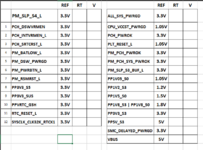
On a Macbook board up to the fifth generation of Intel, before lifting components, the first thing you should do is take a reading of the voltages and the resistance to ground of the rails that appear in the attached photo (the resistance to ground is measured placing the multimeter on the Diode scale, the red probe on Ground and touching with the black (common) probe each pin or contact of the components you want to measure, for example: 0L means out of range or no connection; 0.0000 connected to ground (short circuit); 0.450 there is a resistance, the component may be OK (no short circuit)).
From the attached image, in the RT column, write down the value of the Earth Resistance, and in V, the value of the voltage that you detect (you can make an excel sheet to save it for future reference), the values recorded in that sheet of calculation (image) are for reference.
IMPORTANT:
On a Macbook motherboard the most important line is PM_SLP_S4_L, this may have a resistor value of (eg 470) which is normal, however on power up it may read 0V, if this is the case, the fault is before creating that signal. On the contrary, if the PM_SLP_S4_L line indicates 0 Ohm when measuring the resistance to ground, there may be a problem in the PCH or CPU, in this case it is not worth pursuing or insisting on repair.
The attached test is known as "Test 11+1"
CopyRight
Ownership and credits of Notebook Centro BestChoice CHILE
The use of this information is only authorized on the Dr. BIOS site and its partners outside the Internet.